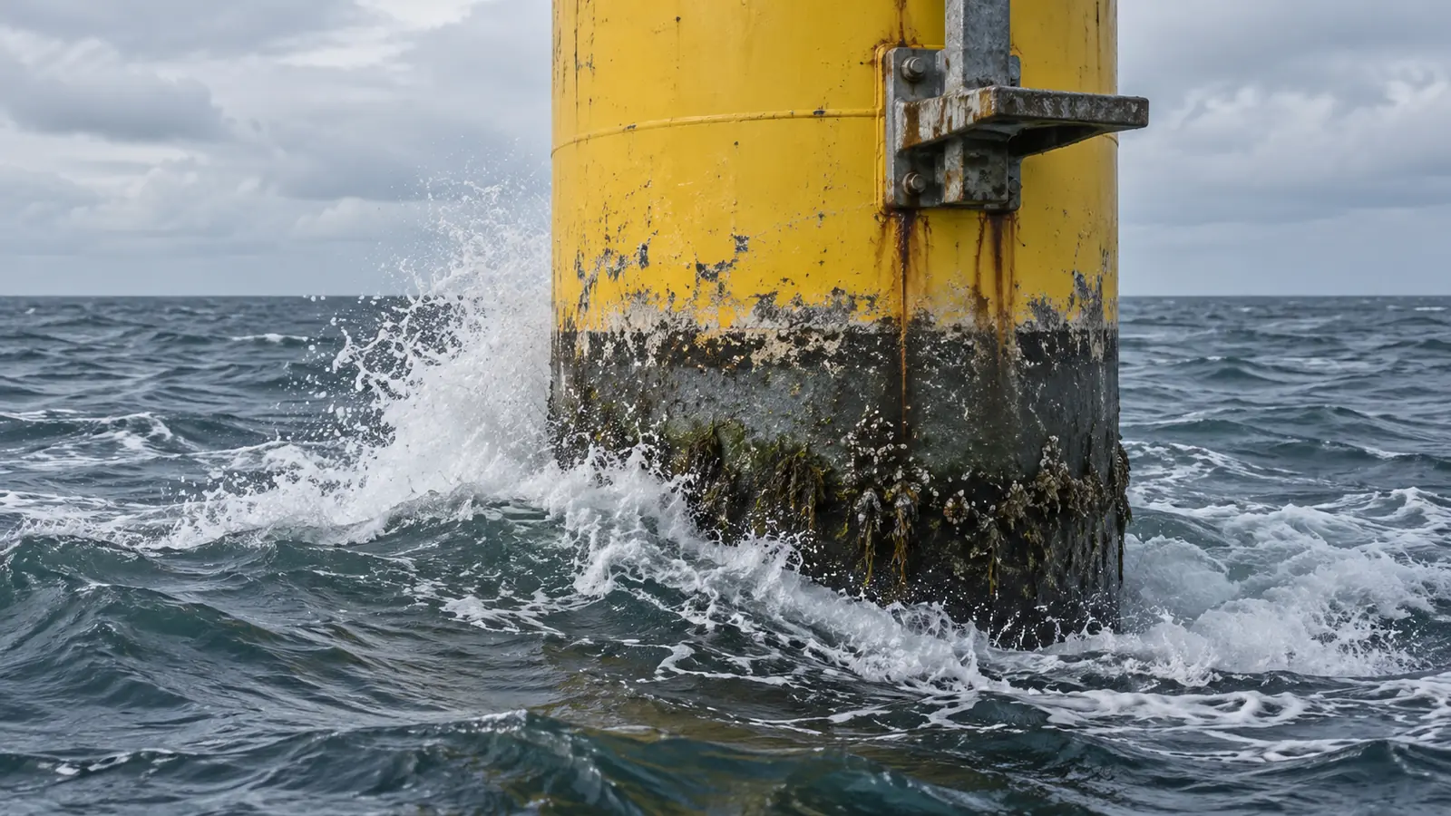
Marine cathodic protection prevents underwater corrosion on submerged steel structures by supplying direct electrical current that forces the steel surface to act as the cathode of an electrochemical cell. Without a working cathodic circuit or when protective voltage drifts out of range, seawater attacks bare-metal holidays and permeable paint films, causing localized pitting, coating disbondment, and costly structural damage on offshore foundations, coastal gates, and subsea hardware.
While atmospheric and splash-zone steel rely primarily on heavy-duty barrier and zinc-rich coatings—covered in our companion analysis of marine paint for metal—continuous immersion creates a closed electrolyte circuit where paint and cathodic protection must operate as a coupled engineering system. This technical review examines the four-part corrosion circuit, the engineering trade-offs between galvanic (sacrificial) anodes and impressed-current cathodic protection (ICCP), the documented boundaries of DNV offshore standards, and the field evidence on how overprotection blisters barrier coatings.
| Protection Method | Current Source & Circuit Path | Relationship to Submerged Steel | Primary Operational Constraint | Typical Marine & Coastal Application |
|---|---|---|---|---|
| Barrier Coating Alone | None (electrical insulator between steel and water) | Isolates steel from the seawater electrolyte until film holidays or ion migration occur | Pinholes, mechanical impact, and progressive water uptake allow localized anodic pitting | Atmospheric, splash-zone, and above-water structural steel; primary current-reduction layer underwater |
| Galvanic (Sacrificial) Anode CP | Natural electrochemical potential difference from an active alloy (Al or Zn) | Welded standoff core or bonding strap provides direct metallic return path; seawater completes ionic loop | Finite anode mass consumes over time; fixed driving voltage cannot be dialed back remotely | Submerged monopiles, jacket braces, floating wind hulls, subsea templates, and coastal hydraulic gates |
| Impressed-Current CP (ICCP) | External DC power supply (rectifier) wired to low-consumption anodes | Insulated positive feeder cable to anodes and negative return cable to steel structure | Requires continuous power, intact cable insulation, and reference-electrode voltage control to prevent overprotection | Ship hulls, large concrete-and-steel port terminals, and utility-connected hydraulic gates |
| Combined Barrier Coating + CP | Barrier film reduces exposed steel area; galvanic or ICCP polarizes remaining holidays | Coating limits required protective current while CP prevents dissolution at film defects | Excessive negative potential around anodes or sharp corners generates hydrogen gas and blisters the coating | Multi-decade submerged offshore wind foundations, wave energy converters, and lock/dam radial gates |
The Four-Element Corrosion Cell in Seawater
As documented in the U.S. Bureau of Reclamation (USBR) Guide to Protective Coatings, Inspection, and Maintenance (April 2012, Chapter I, pp. 4–5), metallic corrosion in water is an electrochemical reaction that requires four components operating at the same time:
- Anode: The more electrochemically active metal site where oxidation occurs and metal ions dissolve into solution (where visible rust and section loss develop on unprotected steel).
- Cathode: The less active metal site where reduction reactions consume electrons arriving from the anode without losing metal mass.
- Electrolyte: Water containing dissolved salts and ions capable of conducting ionic current from the anode to the cathode.
- Metallic return path: A continuous metal-to-metal electrical connection allowing electrons released at the anode to travel back to the cathode.
On an unprotected submerged steel pile or gate leaf, microscopic variations in mill scale, weld heat-affected zones, oxygen concentration, and coating damage create thousands of local anodes and cathodes across the same piece of steel. Seawater provides a low-resistivity electrolyte, and the steel plate itself acts as the metallic return path.
Cathodic protection intervenes by introducing an external anode into the same electrolyte and connecting it electrically to the steel structure. By supplying enough electrons to polarize every exposed steel site to a uniform cathodic potential, anodic dissolution on the structure stops and transfers instead to the external anode.
Why Coated Submerged Steel Still Requires Cathodic Protection
A common misconception outside marine engineering is that applying a thick multi-coat marine epoxy eliminates the need for cathodic protection below the waterline. Field inspection data from the U.S. Army Corps of Engineers (USACE) Engineer Research and Development Center report Evaluation of Coating Systems and Cathodic Protection for Navigation Gate Leaf Structures (ERDC/CHL CHETN-IX-43, September 2016, pp. 6–9) demonstrates why neither standalone paint nor bare-metal cathodic protection is sufficient on long-life submerged structures:
- Application holidays and mechanical damage: Even factory-blast-cleaned steel develops microscopic pinholes (holidays) during field mixing and spray application (
CHETN-IX-43, pp. 6–7). During pile driving, offshore lifting, or debris impact, localized scrapes expose bare steel directly to seawater. On an otherwise well-coated structure without cathodic protection, anodic current concentrates at those small holidays, accelerating deep pitting. - Water and ion permeation through intact epoxy films: Barrier coatings—such as epoxies, coal tar epoxies, and aromatic polyurethanes defined in the USBR guide (2012, p. 8)—slow down electrolyte contact, but they are not permanently impermeable. USBR electrochemical impedance spectroscopy (EIS) studies cited in
CHETN-IX-43(p. 8) show that commercial epoxy coatings experience a measurable drop in electrical impedance over immersion time as water and dissolved ions migrate into microscopic pores in the polymer film, initiating under-film corrosion long before rust breaks through the surface. - Service-life extension when coating and CP work together: Combining a barrier coating with cathodic protection sharply reduces the exposed metal surface area that requires protective current, while the cathodic circuit prevents rust at holidays and declining-impedance zones. In
CHETN-IX-43(p. 8), USACE and USBR report that on the 1985 epoxy-coated radial gates at Yellowtail Dam on the Bighorn River, pairing cathodic protection with the epoxy barrier extended functional performance to more than 30 years, roughly doubling the 15-to-20-year service life typically achieved by a standalone submerged coating system.
Takeaway: Barrier coatings reduce the electrical current needed to protect submerged steel, while cathodic protection arrests corrosion at unavoidable pinholes, impact scrapes, and aging polymer pores.
Galvanic Anodes vs. Impressed-Current (ICCP) Systems
Marine engineers deploy cathodic protection through two distinct circuit architectures: galvanic (sacrificial) anode systems and impressed-current cathodic protection (ICCP).
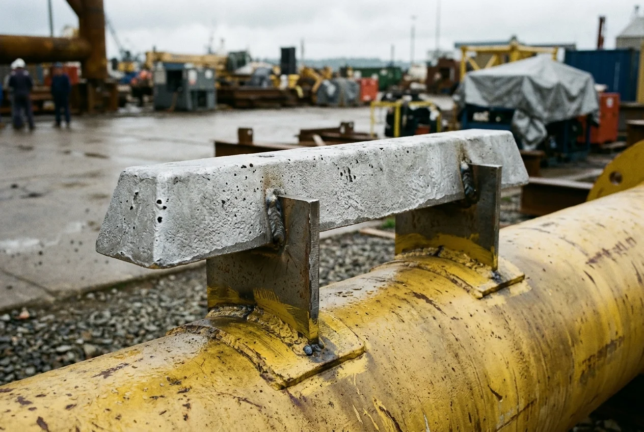 Figure 1 — A cast aluminum-zinc sacrificial standoff anode welded via steel brackets onto a coated tubular foundation member. The steel core feet are welded and touch-up painted to maintain low-resistance metallic continuity, while the rough-cast anode face remains bare to discharge ionic current into seawater.
Galvanic (Sacrificial) Anode Cathodic Protection
Galvanic systems rely on the natural electrochemical potential difference between structural carbon steel and a more active metal alloy—predominantly aluminum-based or zinc-based alloys in seawater. Cast standoff or flush-mounted anodes are welded directly to the steel substructure via cast-in steel core straps or bolted with verified bonding jumpers.
Because the driving voltage is fixed by the alloy’s electrochemistry, galvanic systems require no external power cables, rectifiers, or active control electronics. That simplicity makes galvanic standoff anodes the standard choice for submerged offshore wind monopiles, jacket braces, and floating offshore wind substructures where subsea cable penetrations and active transformer-rectifier maintenance are impractical.
Stationary marine infrastructure also differs fundamentally from small vessels. Recreational boat maintenance guides (such as CMP Group’s Boat Anodes 101) assume vessels are hauled out annually so owners can visually check and unbolt depleted zinc or aluminum hull plates. An offshore foundation or submerged tidal frame cannot be drydocked; its galvanic anode array must be sized and distributed during fabrication to last the planned submerged design life or until scheduled ROV intervention.
Impressed-Current Cathodic Protection (ICCP)
Impressed-current systems connect an external direct-current (DC) power supply (a transformer-rectifier) between the steel structure (wired to the negative terminal) and specialized low-consumption anodes (wired to the positive terminal). Because the rectifier can raise output voltage and current to match changing water resistivity, flow velocity, and coating breakdown over decades of service, a small number of ICCP anodes can protect large surface areas.
However, ICCP introduces mechanical and electrical vulnerabilities in high-energy marine environments:
- Wave loading, debris impact, or ice and sediment abrasion can sever anode leads or damage dielectric shields near the anodes.
- If the reference-electrode feedback loop fails or a rectifier is manually adjusted too high without continuous potential monitoring, an ICCP system can drive local steel potentials far past safe coating limits (
CHETN-IX-43, p. 7).
Takeaway: Galvanic standoff anodes dominate unmanned offshore foundations because they need no external power or control wiring, whereas ICCP suits powered vessels and accessible port or gate structures where rectifiers and reference cells can be actively maintained.
Offshore Design Standards and Public Scope Boundaries: DNV-RP-B401 and DNV-RP-0416
In offshore energy engineering, two DNV recommended practices govern subsea cathodic protection and corrosion control. Because the full numerical tables of both standards are subscription-controlled documents, engineering specifications must distinguish clearly between what their public scope establishes and what requires licensed project calculations:
DNV-RP-B401(Cathodic protection design, Edition May 2021): According to the official DNV standards catalogue summary,DNV-RP-B401facilitates conceptual and detailed cathodic protection design specifically using aluminium or zinc based galvanic anodes, alongside the specification of anode manufacture and installation. It is a galvanic-anode design and fabrication standard—not an impressed-current (ICCP) manual.DNV-RP-0416(Corrosion protection for wind turbines, Edition March 2016, Amended October 2021): According to the official DNV standards catalogue summary,DNV-RP-0416covers the design, construction, and in-service inspection of corrosion protection systems for wind turbines, with primary emphasis on offshore wind turbine support structures, offshore substations, and meteorological masts. It integrates protective coatings, corrosion allowances, and cathodic protection across the atmospheric, splash, submerged, and buried zones.
Rather than applying generic rules of thumb, offshore structural engineers use DNV-RP-0416 and DNV-RP-B401 together: coating breakdown factors define how much bare steel area must be protected in Year 1 versus Year 25, and local seawater temperature, salinity, and oxygen conditions determine the required anode mass and standoff geometry.
Coating Disbondment, Overvoltage Blistering, and the USACE CHETN-IX-43 Discrepancy
While under-protection allows rust and pitting at coating holidays, overprotection (excessive negative potential) attacks the protective barrier coating itself. When cathodic polarization drives the steel potential too negative, water reduction at the metal-coating interface generates hydrogen gas bubbles and raises local alkalinity (hydroxyl ion concentration). That combination weakens coating adhesion and pushes the paint film outward into fluid-filled domes—a failure mode known as cathodic disbondment or overvoltage blistering.
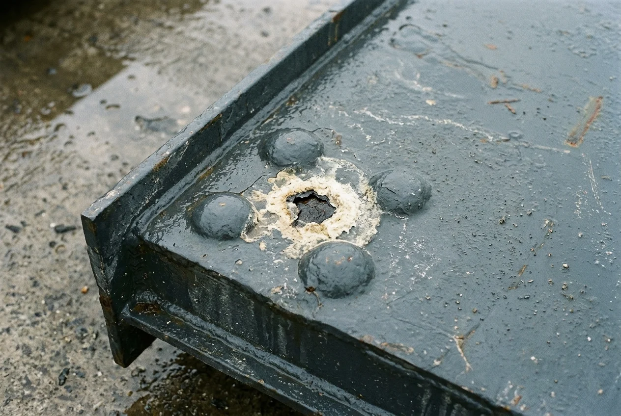 Figure 2 — Close-up of a dark epoxy-coated submerged steel gate plate after dewatering. Dome-shaped cathodic blisters and a ruptured film holiday rimmed with off-white calcareous deposits appear near a welded stiffener corner where local electrical potential concentrated, while the surrounding coating remains intact.
Field Evidence and Internal Source Contradiction in USACE CHETN-IX-43
In USACE ERDC/CHL CHETN-IX-43 (pp. 7–8), researchers documented submerged navigation gates removed after 38 years of service in the USACE Mobile District. Although the cathodic protection system prevented rust across the steel substrate, the paint film was heavily bubbled around the anodes and at structural corners where potential was elevated.
Crucially, CHETN-IX-43 contains an explicit internal discrepancy between its page 7 body text and its page 8 photograph caption regarding which cathodic protection method caused that overvoltage blistering:
- Page 7 body text (
CHETN-IX-43, p. 7) states: “It is common for overvoltage to destroy coatings. This is not a problem for sacrificial anodes, only for impressed current systems which can be turned up above the 1.4 volt threshold. This overvoltage condition may exist when the CP voltage is not continuously monitored.” - Page 8 Figure 3 caption (
CHETN-IX-43, p. 8)—directly beneath the photograph of the blistered gate coating—reads: “Figure 3. Example of failure from CP overvoltage. Sacrificial anode caused blistering of coating.”
Furthermore, the page 7 text mentions a "1.4 volt threshold" without specifying the reference electrode scale (for example, silver/silver-chloride in seawater versus copper/copper-sulfate in fresh or brackish water) or whether the reading represents rectifier terminal voltage or polarized structure-to-electrolyte potential.
Because the primary USACE report contradicts itself between its prose and its figure caption—and leaves the reference scale of the 1.4 V figure unstated—sound marine engineering practice does not treat sacrificial anodes as automatically immune to localized coating disbondment, nor does it apply an unreferenced 1.4 V cutoff across different electrolytes. Instead, coating qualification tests (such as cathodic disbondment testing) and dielectric anode shields or standoff brackets are used to keep peak potential gradients directly adjacent to anodes from stripping the barrier film.
Takeaway: Excessive cathodic potential blisters paint around anodes and sharp structural corners; because primary field literature in USACE CHETN-IX-43 conflicts on whether impressed current or a sacrificial anode caused its documented overvoltage failure, engineers verify polarized potentials against a specified reference electrode rather than relying on uncalibrated voltage rules.
In-Service Inspection: Reference-Electrode Potential Surveys vs. Field EIS
Once a coated and cathodically protected steel structure is submerged, routine visual inspection by divers or remotely operated vehicles (ROVs) tells only part of the story. As CHETN-IX-43 (pp. 8–10) notes, visual inspection is qualitative and subjective: it confirms gross mechanical damage, anode consumption shape, and ruptured blisters, but it cannot tell whether an intact-looking coating has lost its electrical barrier resistance or whether the steel beneath is properly polarized.
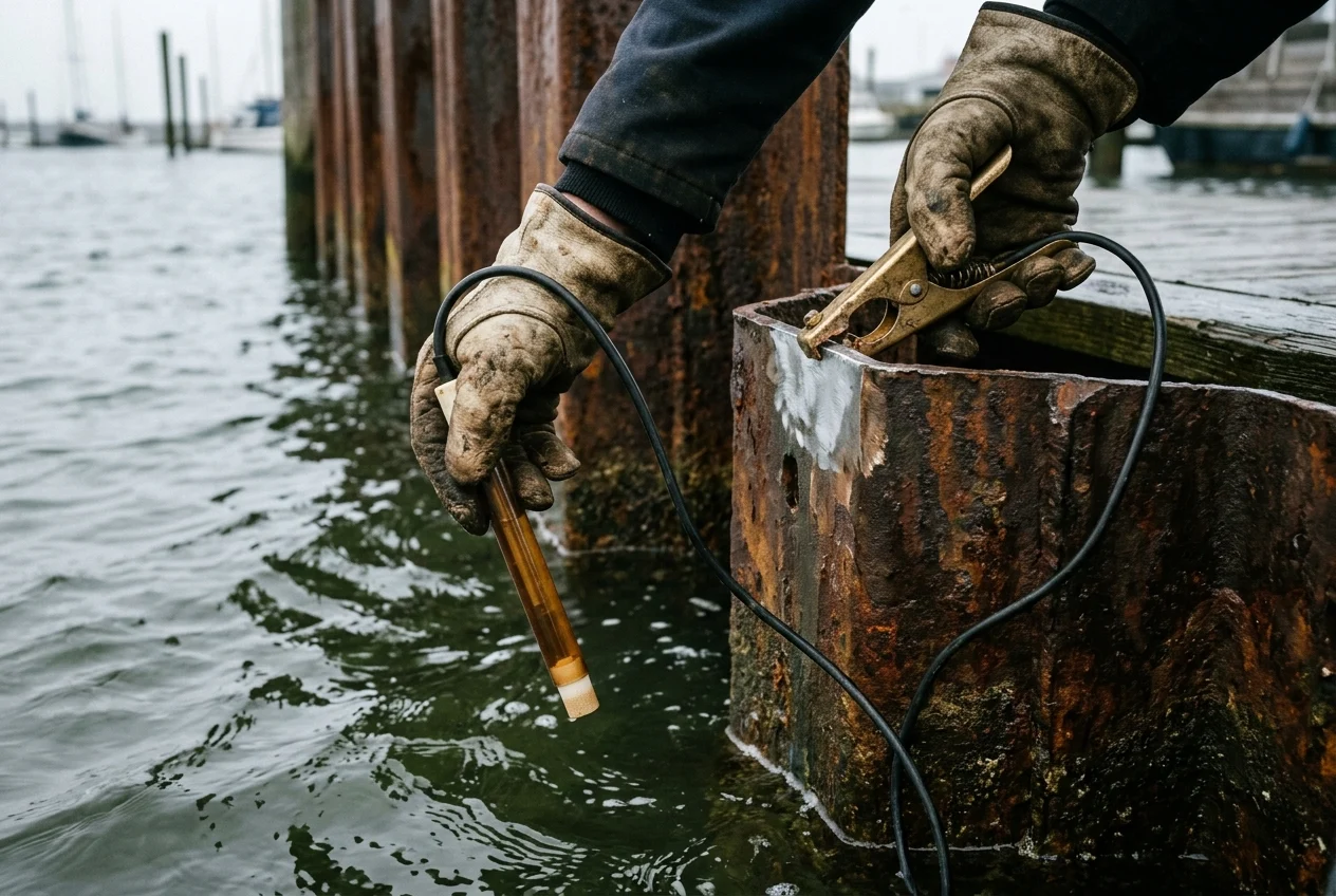 Figure 3 — Two-point electrochemical potential check at a steel harbor wall: a heavy brass clamp makes direct metal-to-metal contact on a freshly ground spot of the steel piling while a reference electrode probe with a porous ceramic plug tip is lowered into the seawater electrolyte.
To evaluate both sides of a coupled coating-and-CP system, maintenance programs combine two distinct electrochemical diagnostic methods:
1. Structure-to-Electrolyte Potential Surveys (Half-Cell Checks)
Measuring whether a submerged structure is receiving adequate cathodic current—without crossing into overvoltage territory—requires a high-impedance voltmeter connected across two points:
- Clean metallic return contact: A ground clamp or contact tip pressed against bare metal on the structure (or a dedicated test-station bonding terminal) to access the electron path. Clipping onto rust scale or intact epoxy breaks the circuit and produces invalid readings.
- Immersed reference electrode (half-cell): A calibrated reference electrode lowered into the water near the steel surface being surveyed, establishing a stable electrochemical benchmark through its porous tip.
Recording structure-to-electrolyte potentials at multiple elevations—especially near anodes, weld nodes, and recessed corners—reveals both under-protected shadow zones and over-polarized hotspots before coating disbondment spreads.
2. Field Electrochemical Impedance Spectroscopy (EIS) for Coating Health
While half-cell surveys measure the cathodic protection potential, they do not directly measure the remaining barrier integrity of an intact paint film. In CHETN-IX-43 (p. 10), USACE highlights the U.S. Bureau of Reclamation’s use of portable field electrochemical impedance spectroscopy (EIS) on submerged hydraulic gates.
By applying a low-amplitude alternating-current signal across a test cell attached to the coated steel, field EIS measures the impedance (pore resistance and capacitance) of the polymer film. According to CHETN-IX-43 (p. 10), USBR’s field EIS technique can detect under-film corrosion down to 0.0001% corroded area within the inspected patch—identifying moisture permeation and early barrier breakdown years before visible blistering or rust appears.
Takeaway: Complete submerged asset monitoring pairs reference-electrode potential checks (which verify that the cathodic circuit is polarizing the steel within safe bounds) with quantitative coating assessments such as field EIS (which detect water uptake and under-film degradation before visible failure).
Frequently Asked Questions
Why can’t marine barrier paint replace cathodic protection on submerged offshore structures?
Even heavy-duty marine epoxies develop microscopic pinholes during field application and suffer scrapes during transport, pile driving, or debris impact. In addition, USBR electrochemical impedance spectroscopy (EIS) testing documented in USACE ERDC/CHL CHETN-IX-43 (p. 8) shows that water and ions gradually migrate through intact epoxy films, lowering coating impedance over time. Cathodic protection polarizes those bare-metal defects and aging film pores so anodic pitting cannot concentrate at small holidays.
Does DNV-RP-B401 cover impressed-current cathodic protection (ICCP) design?
No. According to DNV’s official standard scope for DNV-RP-B401 (Cathodic protection design, Edition May 2021), the recommended practice facilitates conceptual and detailed design of cathodic protection using aluminium or zinc based galvanic anodes, including specification of anode manufacture and installation. System-level corrosion protection across offshore wind turbine support structures, offshore substations, and meteorological masts is addressed under DNV-RP-0416.
Can cathodic protection damage marine coatings?
Yes. When local cathodic potential becomes excessively negative—often near anodes, sharp structural corners, or unmonitored impressed-current rectifiers—electrochemical reduction generates hydrogen gas and alkaline hydroxyl ions at the steel-coating interface, causing cathodic disbondment and dome-shaped paint blisters (USACE ERDC/CHL CHETN-IX-43, pp. 7–8). Because CHETN-IX-43 contains an internal conflict between its page 7 text (which attributes overvoltage blistering solely to impressed-current systems above 1.4 V) and its page 8 Figure 3 caption (which attributes the pictured blistered gate coating to a sacrificial anode), engineers control both anode standoff geometry and monitored reference-electrode potentials to protect the coating.
Why must a reference-electrode survey clamp onto bare steel instead of painted metal?
A half-cell potential measurement requires a closed electrical circuit between the voltmeter, the steel substrate, the seawater electrolyte, and the reference electrode (USBR 2012, pp. 4–5). Barrier coatings and heavy rust scale act as electrical insulators; clamping onto painted or oxidized metal prevents electron flow or introduces contact resistance error, making it impossible to measure the true polarized potential of the submerged steel.