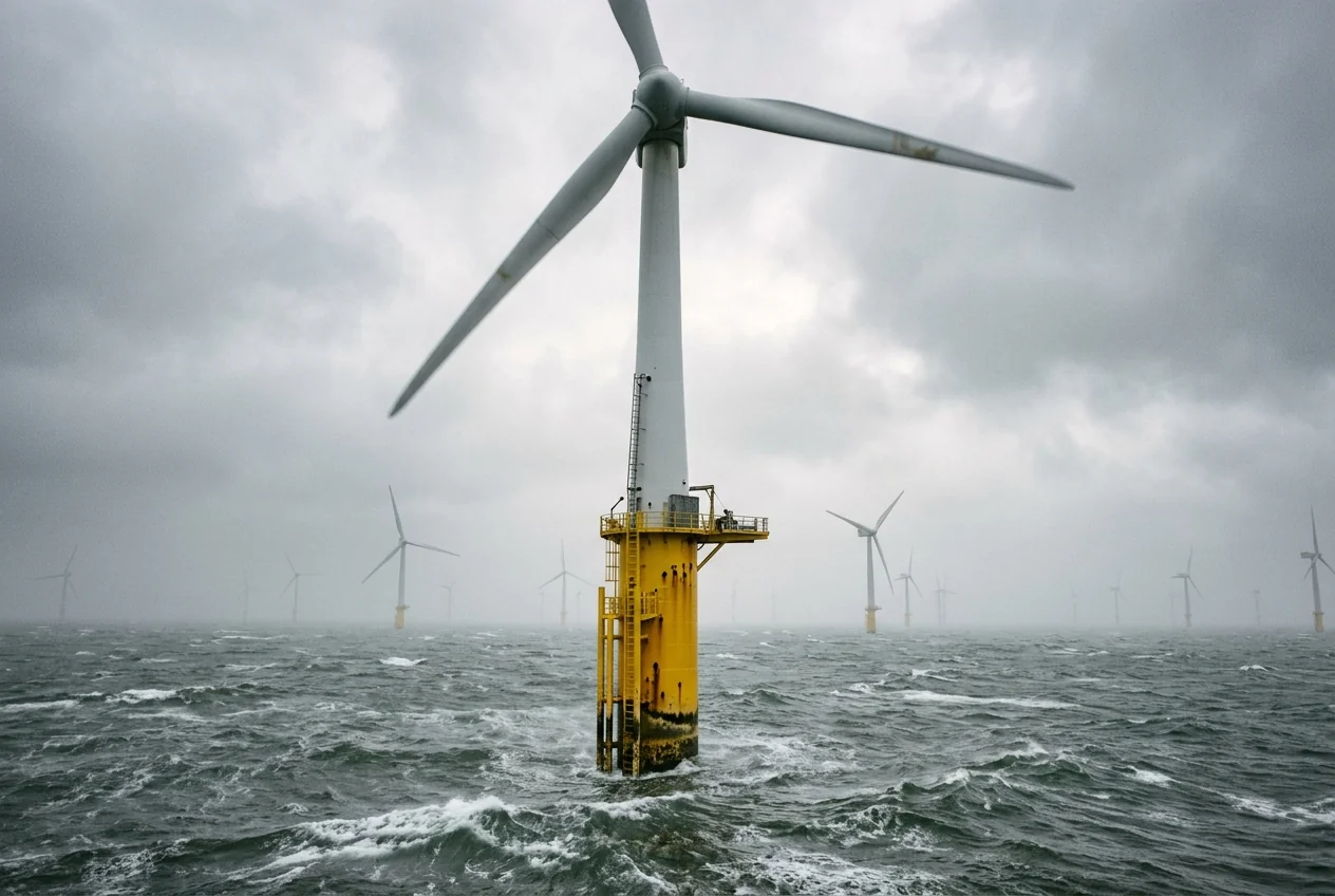
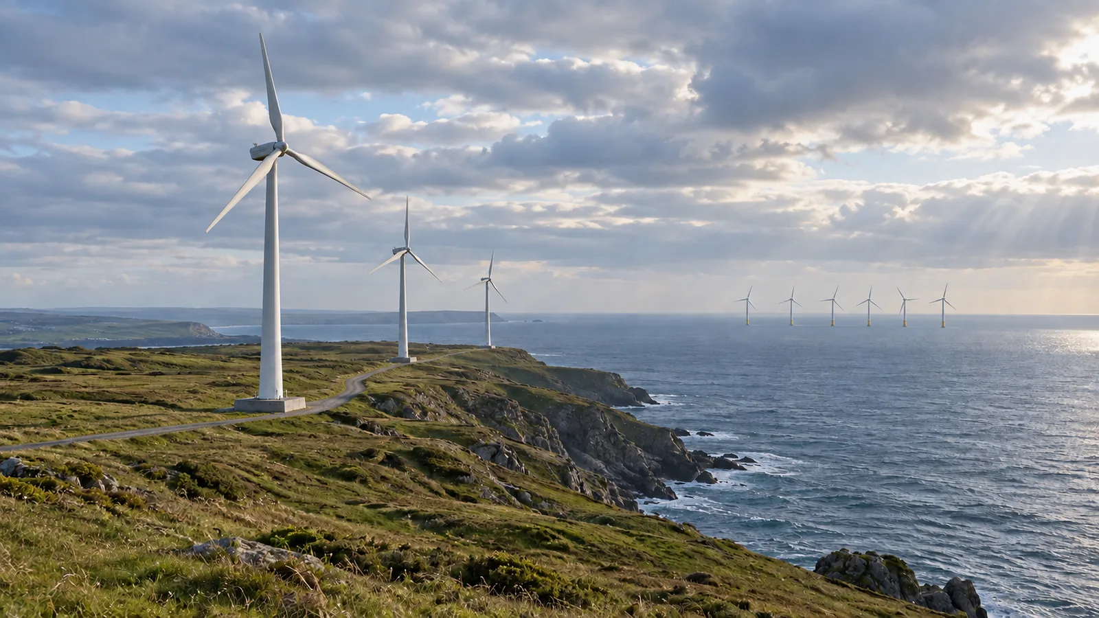
Treating every floating wind turbine as something that can simply be towed back to port hides an important design difference. Fixed offshore wind uses supports attached to the seabed; floating offshore wind uses buoyant platforms held in position by moorings and anchors.
The comparison turns on the support, its seabed connection, cable movement and the proposed maintenance method. Water depth helps screen the options, but it does not settle the choice by itself. This guide puts those interfaces side by side and explains why a tension-leg platform needs different treatment from a semi-submersible.
For the electricity route above and beyond these supports, start with how offshore wind farms work. For the separate land-versus-sea comparison, see offshore versus onshore wind.
Compare what sits below the turbine
The U.S. Department of Energy’s 2023 offshore wind report, “Offshore Wind Technology Types,” page vii, distinguishes seabed-fixed structures from buoyant supports connected by moorings. BOEM’s August 2024 cable overview, Section 2, pages 3–5, adds the electrical interface.
| Interface | Fixed-bottom offshore wind | Floating offshore wind | What to find in a proposal |
|---|---|---|---|
| Turbine support | Seabed-fixed structure, such as a monopile or lattice jacket | Buoyant platform | Named support concept and its design basis |
| Seabed connection | Foundation transfers loads to the seabed | Mooring lines and anchors hold position | Foundation or anchor arrangement, with site evidence |
| Array cable connection | Typically a seabed-buried array route in BOEM’s overview | Dynamic sections accommodate platform movement | Cable profile showing moving and seabed sections |
| Major maintenance | Ask for the offshore repair and lifting plan | Ask whether work stays offshore or uses an approved tow-to-port method | Platform-specific repair procedure and required facilities |
The last column is an editorial reading checklist, not a foundation specification. “Floating” still involves a seabed connection. It also leaves open which platform, mooring arrangement and maintenance strategy the project uses.
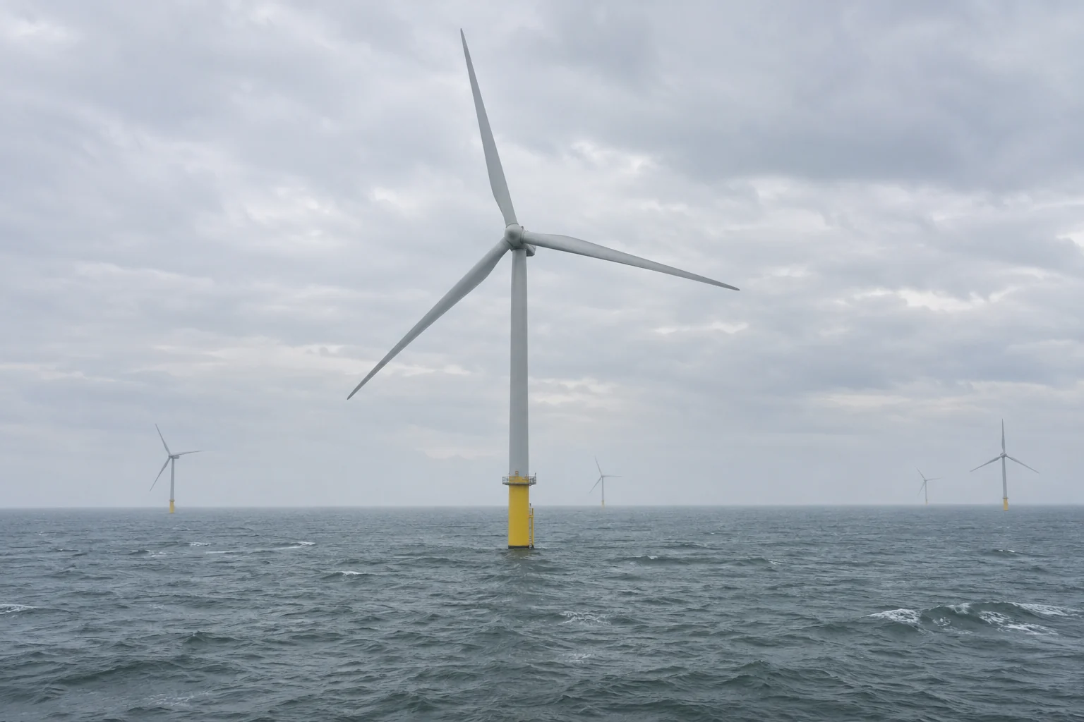
A surface view can show a support at the waterline. It cannot establish the buried foundation geometry, soil conditions or design loads. Keep those fields unknown unless the project documents provide them.
Is 60 metres the boundary between fixed and floating?
It is a useful screening reference, not a hard engineering limit. DOE’s 2023 report describes fixed-bottom deployment as typically in water depths of 60 metres or less and floating deployment as typically deeper. Its footnote explicitly allows floating supports in shallower water depending on siting and economic feasibility.
Use depth to frame the next question: what support concept has actually been assessed for this site? BOEM also identifies geology and oceanographic conditions as design inputs. A depth label alone does not answer that question.
When reading two proposals, record the stated depth and support type separately. Avoid turning a general resource map into an instruction that every site on one side of a contour must use the same foundation.
Floating platform types change the port and stability questions
DOE’s December 2017 floating-wind explainer describes ballast and platform geometry as ways of stabilizing a turbine on a buoyant support. A spar uses a deep submerged mass; a semi-submersible spreads buoyancy across connected elements. That explains the physical distinction, without making its historical project examples evidence of today’s deployment status.
The Guide to a Floating Offshore Wind Farm gives the following platform-specific constraints:
| Platform | Stability or geometry feature | Installation and maintenance implication |
|---|---|---|
| Semi-submersible | Connected buoyant columns, typically with ballast | Relatively shallow draft can allow quayside turbine assembly and stable tow-out |
| Barge | Broad hull area at the waterline | Sheltered-harbour assembly and tow-out are possible for the arrangements described |
| Spar | Deep cylinder with ballast low down | Deep draft constrains assembly locations and towing routes |
| Tension-leg platform, or TLP | Stability depends on continuously tensioned tendons | Specialist transport and installation; ordinary tow-to-shore assumptions do not carry across |
Draft means how far the floating structure extends below the water surface. For a reader checking port access, the practical question is whether the proposed assembly and towing route accommodates that structure.
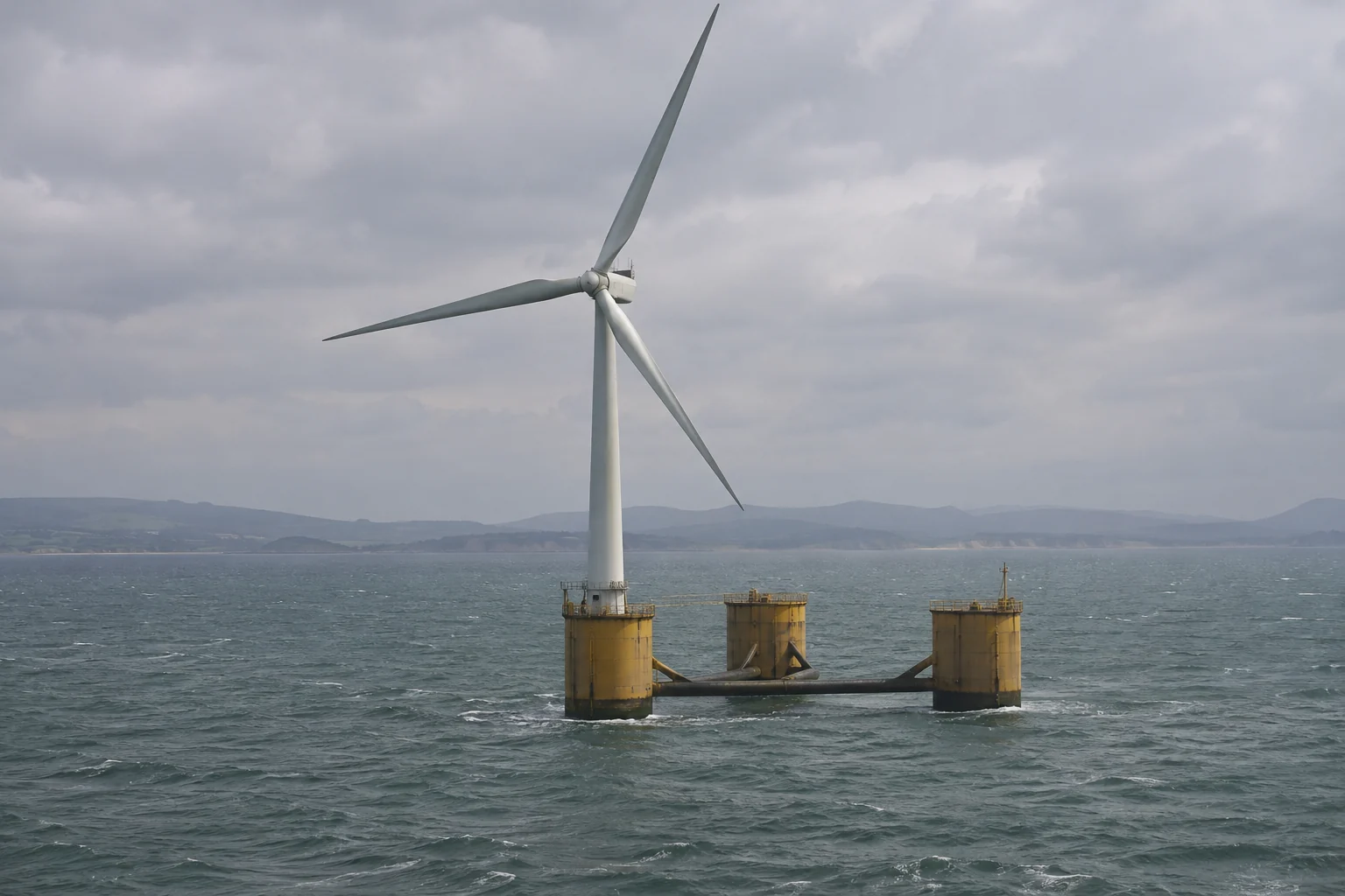
This view makes the broad support visible. Its underwater moorings and anchors remain out of sight; their arrangement needs a drawing rather than an inference from the photograph.
Dynamic cables and moorings do different jobs
Moorings restrain the platform; cables carry electricity. BOEM’s Section 2 describes dynamic inter-array cable sections suspended in the water to accommodate floating-turbine movement. Some designs have buried or weighted sections between the moving ends. Its overview describes export cables as typically buried for both fixed and floating farms.
So neither “all floating-wind cables hang in the water” nor “all subsea cables are buried” is a useful reading rule. Trace each section and identify its role.
On a public cable drawing, mark the turbine connection, moving section, seabed section and onward export route. Ask which parts of the drawing are schematic and which show the project’s selected arrangement. Leave any unstated cable depth or rating blank; the word “dynamic” does not supply either value.
Can floating turbines be towed back to port for repairs?
Do not assume it from the word floating. The Guide’s TLP discussion explains that tendon tension is part of stability. It describes more complex installation and harder tow-to-shore maintenance options than for other floating types. Spars have a different constraint: their deep draft limits suitable routes and facilities.
Our reading recommendation is to look for an explicit repair method. A general statement that assembly can happen at a quay does not, by itself, document how an operating unit would be disconnected, transported, repaired and returned.
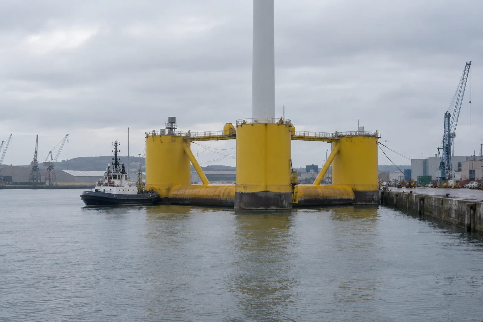
When a proposal mentions tow-to-port maintenance, check whether it identifies the platform configuration, disconnection and reconnection method, route and receiving facility. If those details are absent, record the method as unconfirmed rather than treating the picture of a harbour as proof.
Read a proposal with five checks
Use these questions to turn the comparison into a record of what is known:
- Name the support. Is it a monopile, jacket, semi-submersible, barge, spar or TLP? If the document says only “floating,” keep the type open.
- Locate the seabed interface. Find the foundation or anchor layout and its supporting site information. Do not infer either from depth alone.
- Trace structural and electrical connections separately. Identify moorings, tendons and power cables without treating them as interchangeable lines.
- Find the maintenance route. Record offshore repair or the documented tow-to-port method, including the platform-specific conditions.
- List missing inputs. Write “not stated” beside omitted depths, cable specifications, anchor details or repair procedures. These are questions for the underlying documents.
The useful conclusion is conditional: a proposal is easier to assess when its support, seabed connection, cable profile and repair method are described together. This comparison does not choose a site or declare one support universally preferable.
Sources and scope
Sources were opened on October 16, 2026. DOE’s 2023 report supports the fixed/floating distinction and qualified depth reference; its 2017 article supplies enduring floating-support principles. BOEM 2024-055 supplies the cable distinctions. The Guide supplies platform-specific installation and maintenance constraints; its historical project counts are not used here.
The tables and reading checklist organize those sources for general readers. They do not establish a particular project’s feasibility, price, output or approval. Continue through the offshore wind section for related explainers.