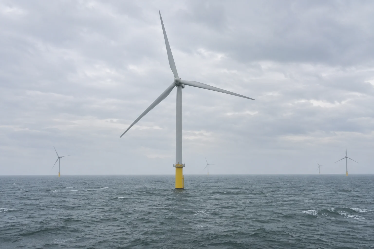
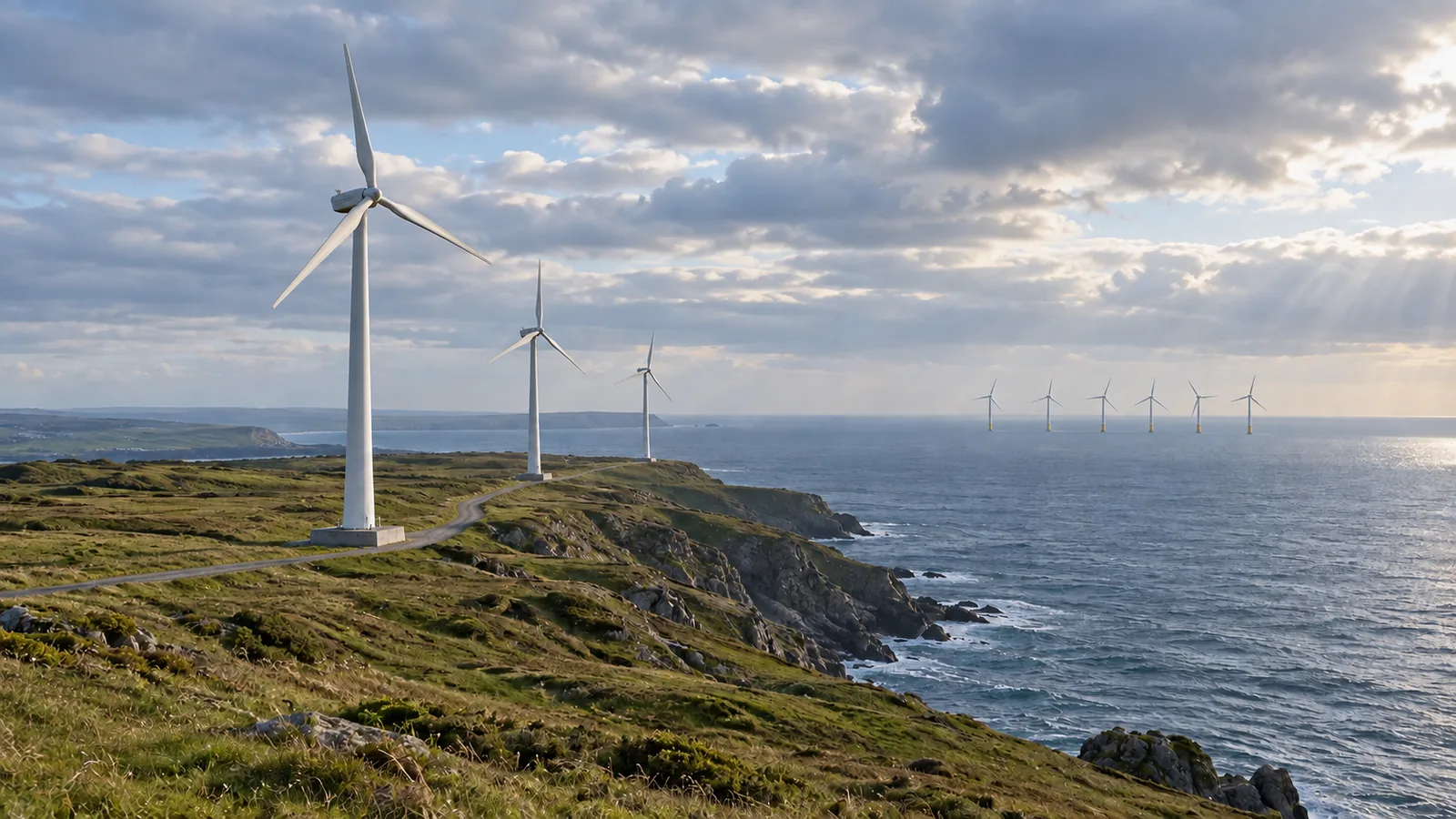
A view of spinning offshore turbines leaves most of the electricity route out of sight. Offshore wind farms turn wind into mechanical rotation, generate electricity inside the turbines, collect it through array cables and send it ashore through an export connection.
The generator is where mechanical rotation becomes electrical power. The cables after it carry electricity; foundations and moorings keep the generating equipment supported. This distinction makes the whole system easier to follow.
This guide traces the equipment in a typical arrangement described by the U.S. Department of Energy and BOEM. It covers both fixed-bottom and floating turbines. For costs and siting trade-offs, use our separate offshore versus onshore wind comparison.
Follow the energy from wind to the grid
Read the following flow from left to right. The change of energy form happens before electricity enters the farm’s cable network.
Moving air → rotor and shaft: mechanical rotation → generator: conversion to electricity → array cables: electrical collection → offshore substation: electrical connection and voltage transformation → export cable: electrical transmission to shore → onshore connection and grid.
This combines DOE’s turbine explanation with the typical farm arrangement in BOEM 2024-055, Section 2, pages 3–5. It is a reading guide to the components, rather than an electrical design drawing. A project’s drawings establish its actual connections and equipment.
| Component | What it handles | Its job in the chain |
|---|---|---|
| Blades and rotor | Wind energy becoming mechanical rotation | Capture energy from moving air |
| Shaft and drivetrain | Mechanical rotation | Connect the rotor to the generator, directly or through a gearbox |
| Generator | Mechanical input, electrical output | Produce electricity from rotation |
| Inter-array cables | Electricity | Link turbines and collect their output toward the offshore substation |
| Offshore substation | Electricity | Connect the collection network to the export system; transformation depends on the design |
| Export cable | Electricity | Carry power from the offshore system toward the onshore grid |
| Onshore connection | Electricity | Join the offshore transmission route to the land-based network |
| Foundation or floating support | Structural loads | Support the turbine; it is outside the energy-conversion sequence |
What happens inside an offshore wind turbine?
Air flowing over a blade creates an aerodynamic force that turns the rotor. The rotor drives a generator through the drivetrain. DOE describes two arrangements: a shaft and gearbox that increase rotational speed, or direct drive connecting the rotor to the generator without that gearbox.
The nacelle is the housing at the top of the tower. From a distant photograph, its internal drivetrain cannot be identified. A spinning rotor alone does not tell you which arrangement the machine uses; check the turbine’s documentation before labeling it geared or direct drive.
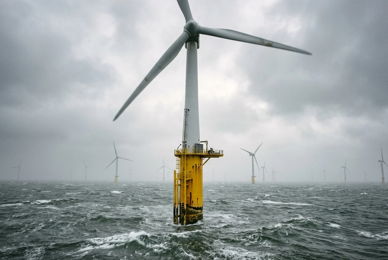
The visible blades are the start of the conversion chain. The generator and the cable connections that continue it are out of view. DOE’s explanation covers the conversion mechanism; it does not establish the model or rating of a turbine in a generic scene.
How does electricity get from the farm to shore?
The array network gathers output within the farm; the export connection takes that collected output toward land. BOEM uses inter-array cable for the links between turbine generators and the offshore substation, and export cable for the transmission connection from the substation to the onshore grid. These names describe different jobs, even though both are submarine power cables.
An offshore substation is an electrical junction in this route. The DOE Atlantic transmission action plan, pages 9–10, describes collection at the substation and a step up in voltage for transmission to shore. In a conventional AC arrangement, transformers provide that voltage change. The exact voltage and number of circuits belong to the project design, so there is no single voltage to insert into this general flow.
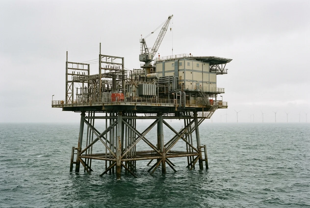
BOEM’s cable report also distinguishes alternating-current and direct-current transmission: its Section 4 describes AC collection cables and either AC or DC export cables. Figure 6 in the DOE action plan shows the converter stations used for a DC export system. Keep that as a conditional branch when reading a project diagram; do not assume every offshore platform contains the same equipment.
At landfall, the marine cable route reaches the coast. The onshore connection continues to the grid. A shoreline photograph therefore shows only one boundary in a longer transmission path, rather than the final destination of all the electricity.
How do floating turbines change the cable route?
Floating offshore wind uses the same wind-to-generator principle. The difference is how the turbine is supported and how its electrical connection accommodates movement.
For the support and maintenance choices below the turbine, see our floating versus fixed offshore wind comparison, including the different port and towing constraints of semi-submersibles, spars and tension-leg platforms.
DOE’s floating-wind explainer, published in 2017, describes buoyant platforms tethered to the seabed. Ballast and platform geometry provide stability in concepts such as spars and semisubmersibles. The turbine floats on its support while moorings restrain it. Those moorings have a structural role; the power cable has an electrical role.
BOEM’s Section 2 explains the corresponding cable distinction:
| Part of the route | Fixed-bottom turbine arrangement | Floating turbine arrangement |
|---|---|---|
| Turbine support | Structure fixed to the seabed, such as a monopile or jacket | Floating support with a station-keeping system |
| Array cable | Typically buried along the seabed route | Dynamic sections extend through the water to accommodate turbine movement |
| Between floating units | Does not require the same platform-motion connection | Some designs use buried or weighted middle sections between moving end sections |
| Export route | Typically buried in BOEM’s overview | Also typically buried in BOEM’s overview; confirm the actual design |
“Subsea” does not mean “buried everywhere.” BOEM specifically describes suspended dynamic cable sections and notes that their depth depends on the design. Its examples include a curved cable profile supported by mid-line buoyancy. A cable drawing should identify those moving sections separately from seabed sections.
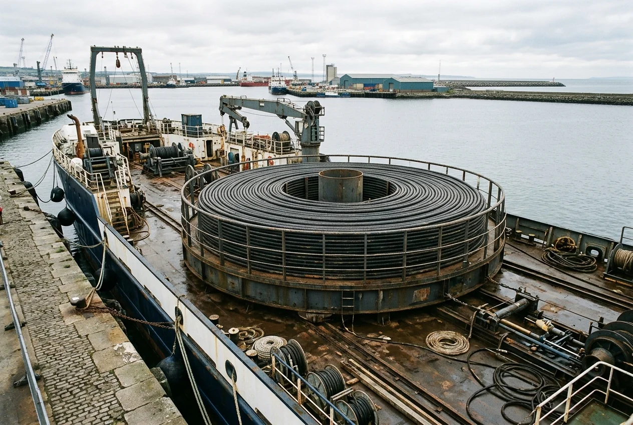
A vessel’s cable load does not reveal the installed route, burial depth or suitability for moving service. Those details must come from the cable specification and the project’s route drawings.
Read a project diagram without mixing up the components
Use the flow and tables above to check five things in a public project description:
- Find the conversion point. Identify the rotor, drivetrain and generator before tracing electrical cables.
- Separate collection from export. Follow array cables to their connection point, then trace the export route toward land.
- Identify the transmission branch. Look for AC transformers or AC/DC converter equipment without assuming a standard configuration.
- Match the cable to the support. A floating platform needs a connection that accommodates movement; check where dynamic and seabed sections meet.
- Continue past the shoreline. Find the onshore connection and grid interconnection rather than stopping at landfall.
If the public drawing omits a voltage, burial depth or equipment rating, leave it unknown. The basic energy chain can still be understood without assigning invented specifications to its components.
For the broader comparison, continue to offshore and onshore wind costs, output and maintenance. For the protective layers used on marine steel, read marine paint systems for metal.
Sources and scope
This is a general explanation assembled from public technical sources, without site measurements or a specific project’s design documents. DOE supports the turbine and floating-support descriptions; BOEM 2024-055 supplies the cable roles and fixed/floating distinctions. The text flow and component tables are editorial summaries of those sources. No turbine rating, cable voltage, operating wind threshold, efficiency or project approval is inferred here.